Tolerance is not a single number applied to an entire drawing. It is a design decision that should follow function: how parts locate, move, seal, fasten, and are inspected. A clearer tolerance strategy usually improves both quotation accuracy and manufacturing reliability.
Start with the functional interfaces. Apply tight limits only where variation changes fit, motion, sealing, alignment, or safety—and define how those features will be measured.
01
Start with function, not the smallest possible number
A machine shop can often manufacture a feature more accurately than a general tolerance block requires. The more useful question is whether that extra accuracy creates value. A mounting face may need flatness to protect alignment, while a clearance pocket on the same part may only need to avoid interference.
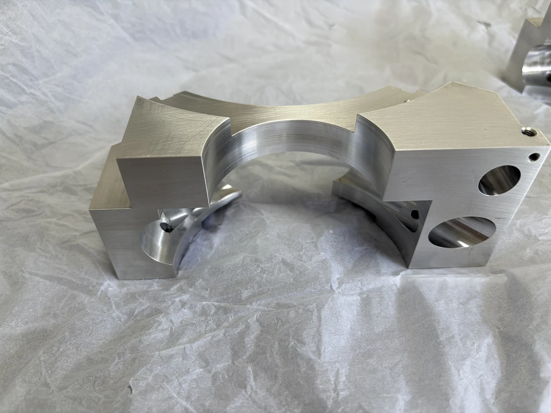
Separate the drawing into functional groups before assigning limits. Interfaces between parts, bearing and seal locations, datum features, and geometry that controls motion deserve the earliest attention. Cosmetic edges, stock-removal pockets, and non-mating exterior profiles can usually accept broader variation.
As a reference point, our standard shop capability holds ±0.1 mm, with as-machined surfaces defaulting to about Ra 1.6 unless the drawing calls for a tighter finish. Where a feature is genuinely functional — a fit, a datum, a sealing land — controlled setups can hold both aluminum and stainless steel down to 0.005 mm; the point of separating functional groups first is deciding which features actually need that level of control.
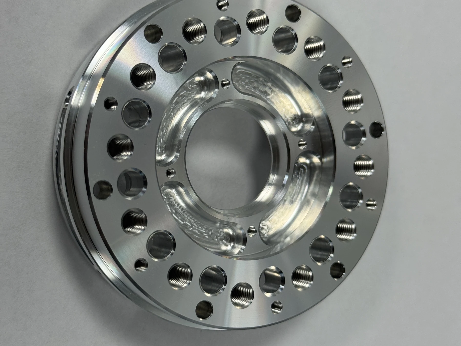
- Fits: shafts, bores, pins, bearings, bushings, and locating features
- Alignment: datums, mounting faces, bolt patterns, and guide surfaces
- Performance: sealing lands, flow paths, optical or RF geometry, and motion components
- Clearance: pockets, covers, guards, and other non-contact geometry
02
Why a tighter tolerance changes the process
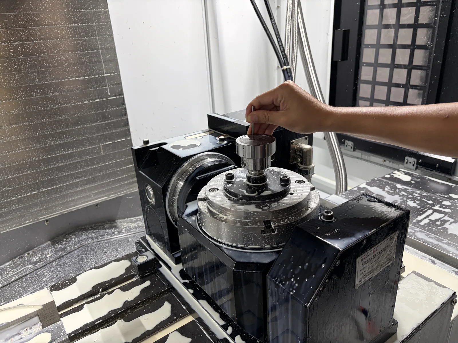
A tight dimension can require more than a slower finishing pass. It may change workholding, tool selection, machine choice, thermal control, inspection frequency, and the number of setups. A tolerance that crosses two setups is especially sensitive because every repositioning introduces another source of variation.
The cost impact grows when a requirement applies to many features or when the measurement method is unclear. If only one bore controls the assembly, identify it. A blanket ±0.01 mm note across an entire part can turn simple geometry into a high-control process without improving performance.
03
Use datums and GD&T to communicate design intent
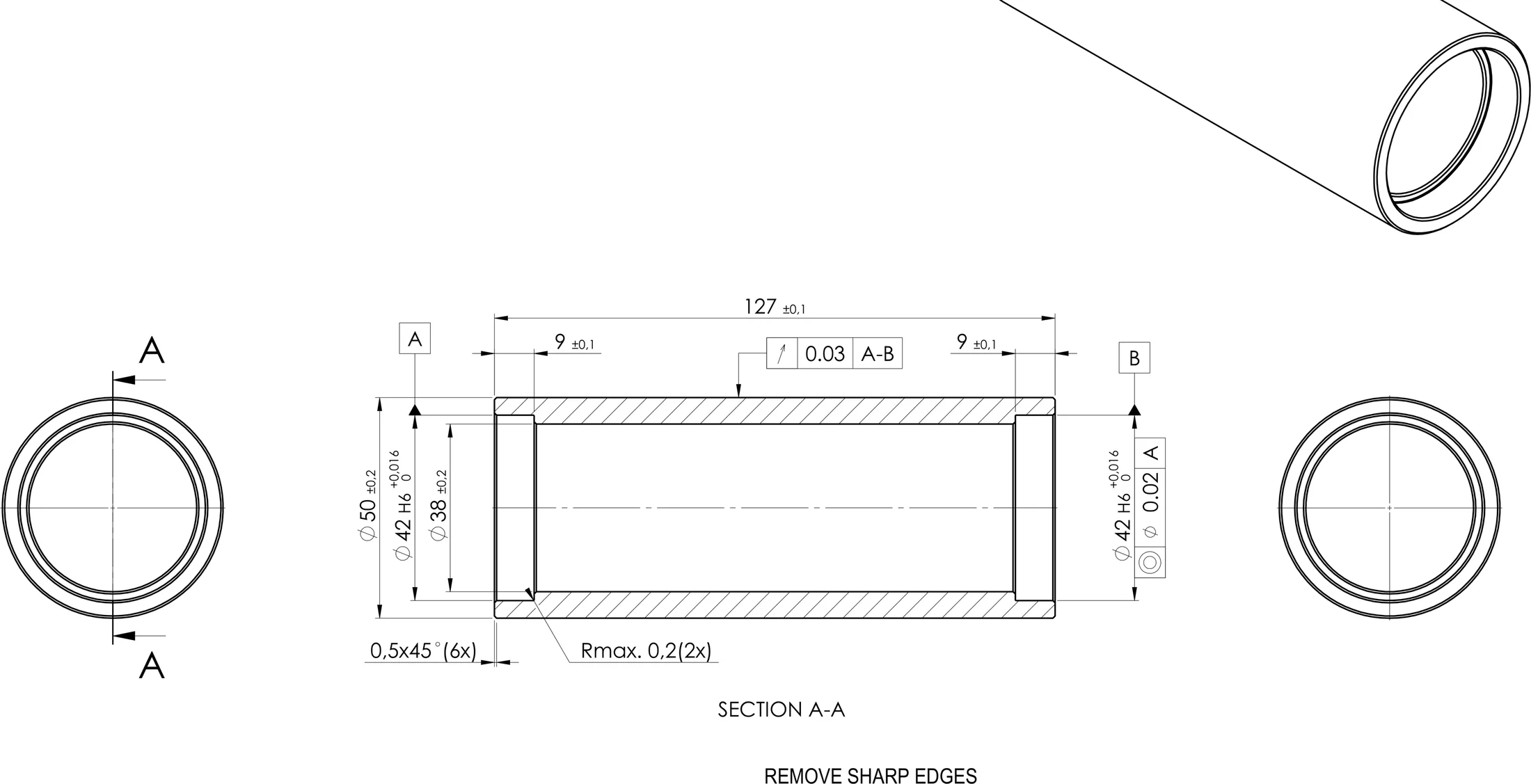
Coordinate dimensions describe size and location, but they may not explain how the part should be set up or inspected. A considered datum structure gives manufacturing and quality teams the same reference system the assembly uses.
Position, flatness, perpendicularity, and profile — the same GD&T conventions defined in ASME Y14.5, not shop-specific notation — can control the relationship that matters more directly than a chain of tight plus/minus dimensions. Keep datum targets physically accessible and stable. A small cast or curved surface rarely makes a dependable primary datum.
04
A better tolerance checklist before RFQ
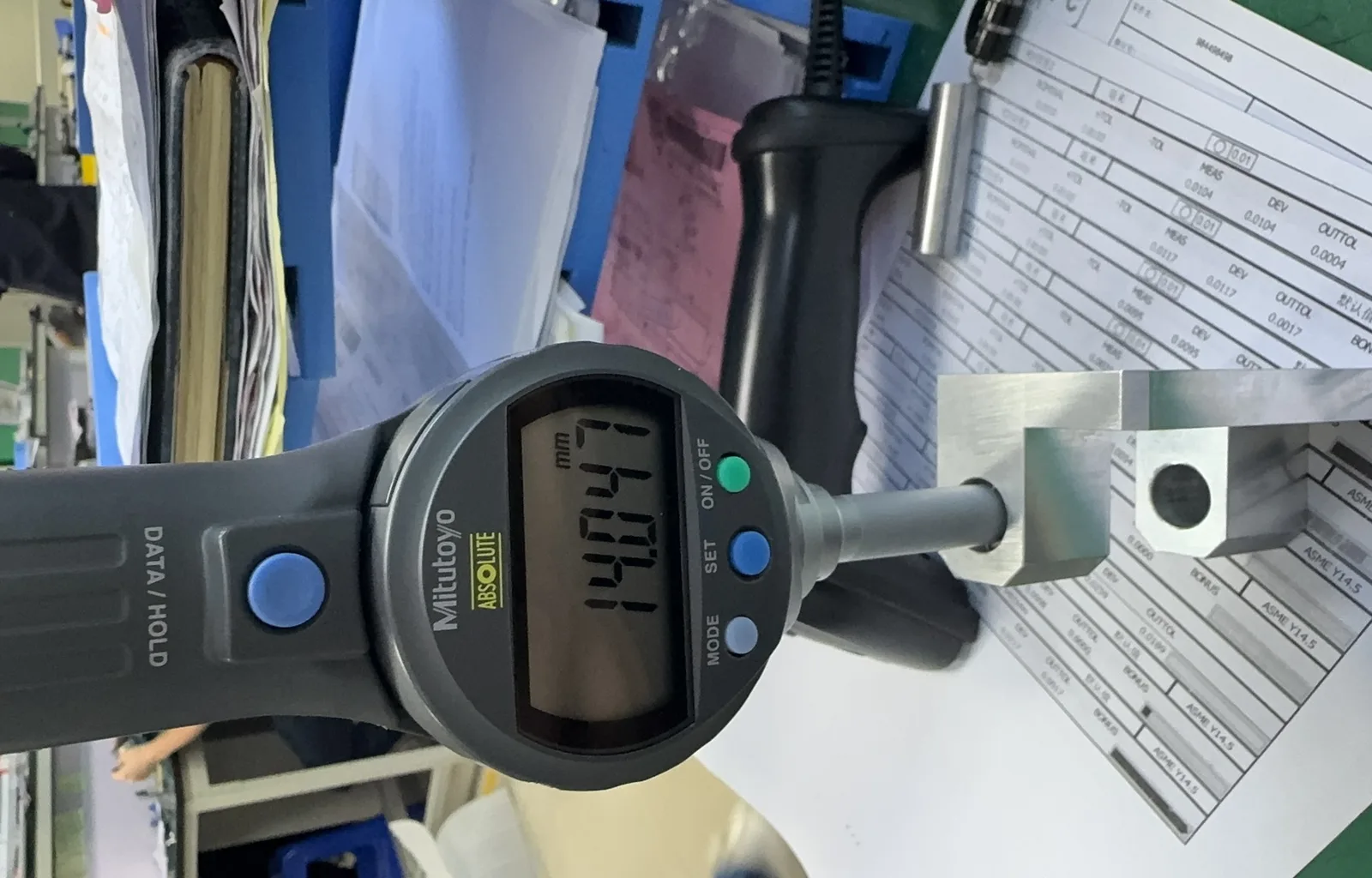
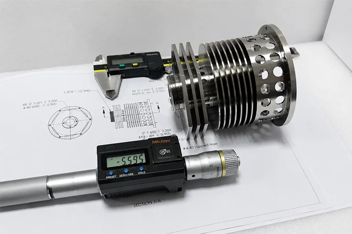
Review the drawing once as an assembler and once as an inspector. Confirm which dimensions create the functional result, whether the datum scheme reproduces assembly conditions, and whether standard inspection equipment can access each feature. Our standard inspection runs on TESA height gauges and Mitutoyo calipers and micrometers — features below what those can resolve reliably need to be flagged so the inspection method is agreed before quoting, not discovered afterward.
When sending an RFQ, include the 3D model, the controlled 2D drawing, material and finish requirements, quantity, and any known mating-part context. Early clarification is faster than resolving an ambiguous requirement after machining begins. OUJI responds within 1 day with next steps, clarification questions or quotation details.
- Mark critical-to-function dimensions rather than relying on color or informal notes
- State limits after coating when the finished surface controls fit
- Avoid closed dimension chains unless the resulting stack-up is intentional
- Agree on the inspection method for difficult or very small features
Sources & technical references
- ASME Y14.5 — Dimensioning and Tolerancing — ASME (American Society of Mechanical Engineers)
Defines the position, flatness, perpendicularity, and profile controls discussed in this guide.