General dimensions
Drawing-defined
Specify individual limits or a general tolerance standard and class. ISO 2768 is applied only when agreed; there is no automatic class for every order.
Start with the drawing
Critical parts · Drawing-led manufacturing
Critical fits, clear requirements and verified features
OUJI manufactures custom CNC parts with critical fits, hole positions and mating surfaces. We review your drawing, plan machining and finishing, and agree how the finished features will be inspected.
Response within 24 hours of receiving complete project details.

Tolerance guide
OUJI reviews tight tolerances at the feature level. Geometry, feature size, material, workholding and datums, order quantity and surface treatment all affect feasibility. The same tolerance can need a different plan on a short diameter, deep bore or thin wall.
General dimensions
Specify individual limits or a general tolerance standard and class. ISO 2768 is applied only when agreed; there is no automatic class for every order.
Start with the drawingPrecision machining
Typical machining tolerance for suitable features after drawing and process review. Size, material, rigidity, setups and finish all affect feasibility.
Suitable features, after reviewSelected critical features
Identify the exact dimension and final condition. The machining route and inspection method must be confirmed for that feature and order.
Feature-specific confirmationKeep tight limits where function needs them. Mark the dimensions that control fit, sealing, alignment or movement. Unnecessarily tight limits on other surfaces can add setup, machining and inspection cost.
ISO 2768 reference toolPlan the critical features
Use the functional requirement to guide the drawing review. Send your existing files; you do not need to redesign the part or choose a machine before contacting us.
For a shaft, bushing or bearing seat, send the mating size, fit designation or explicit limits, engagement length and required surface finish.
CNC turningResolve before production
Confirm the functional axis, finished diameter and measurement access.
Calculate ISO 286 fit limitsFor a housing, fixture or multi-face part, identify functional datums and the relationships that control assembly. A hole diameter alone does not define its position.
CNC millingResolve before production
Agree datum order, setup strategy and the GD&T evaluation basis.
Review position & MMCMark whether acceptance applies after anodizing, plating, heat treatment or grinding. Identify protected bores, contact faces and cosmetic surfaces.
Surface finishingResolve before production
Review masking, machining allowance, re-clamping and access for a final cut.
Review precision grindingReal manufacturing evidence
Published OUJI projects connect the requirement, manufacturing route and available inspection evidence. Each example states exactly what its record supports.
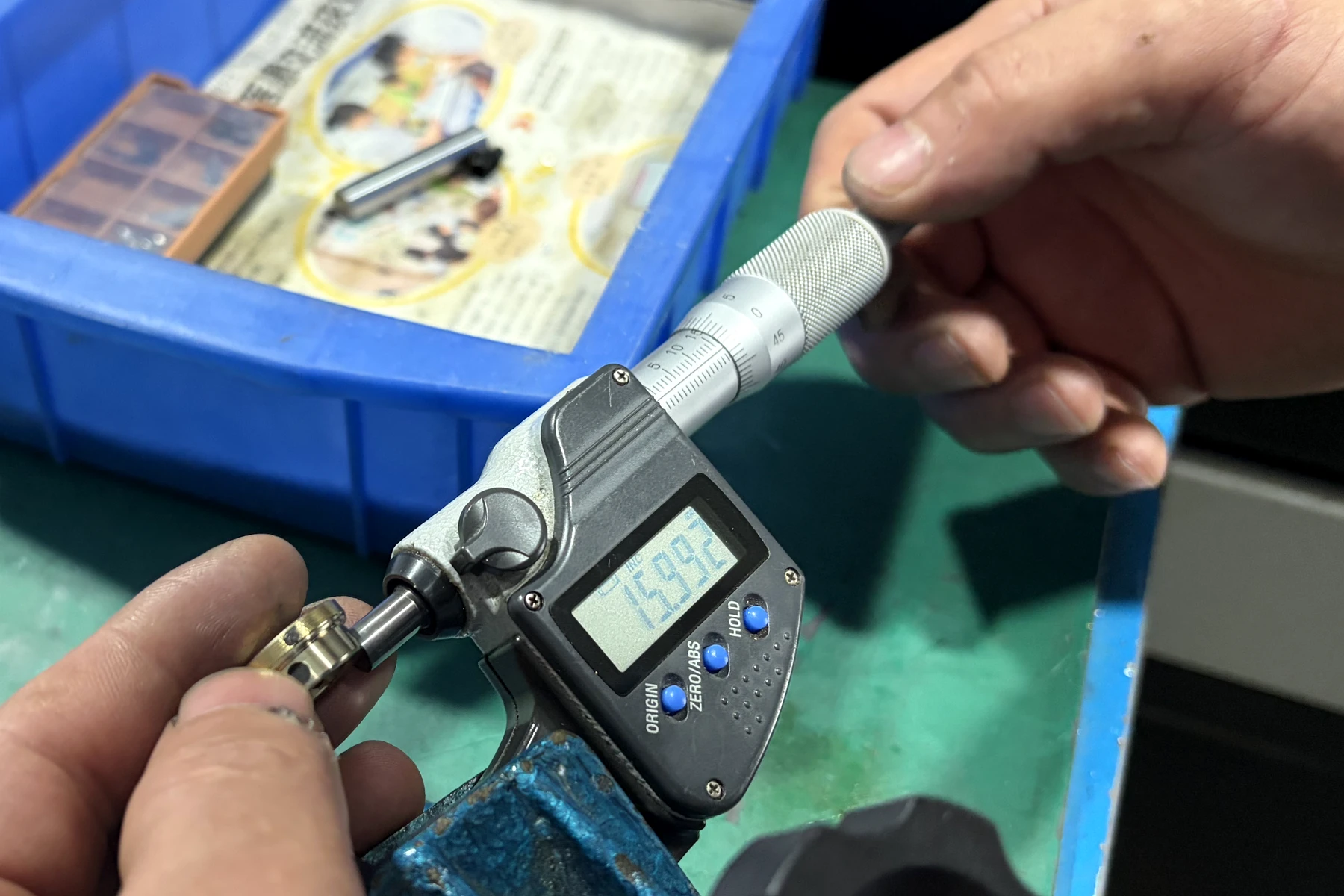
Graphite-insert brass bushing
One published OD check within the stated drawing limits. This photograph does not establish batch capability or verify every feature.
View drawing, process & measurementFollow the drawing datums through 3+2 machining to two published CMM evaluations, including the documented datum-order review.
Grinding & internal burr controlSee the turning and grinding route, a photographed OD check and 100% internal-bore inspection for this project.
Acceptance & inspection
In-house dimensional inspection supports OUJI machining. We select CMM, gauges and other instruments to suit the feature, tolerance and agreed evaluation. Instrument specifications alone do not establish finished-part accuracy.
Critical dimensions, datum relationships and finished condition. The method must suit the tolerance, geometry and access.
Agree sampled checks, first-article approval or specified 100% checks. Full-dimensional reporting and inspection of every part are different scopes.
Confirm the report format, drawing revision, measured results and any material or special-process certificates during quotation.
| Feature to verify | Possible method |
|---|---|
| Length, width, and thickness | Caliper, micrometer, or height gauge |
| Outside and inside diameters | Micrometer, bore gauge, or pin gauge |
| Threads and fits | Plug gauge, ring gauge, or agreed functional check |
| Hole position | Height gauge, fixture, or CMM when required |
| Flatness, runout, and relationships | Surface plate, indicator, fixture, or CMM |
| Profile and complex GD&T | CMM or purpose-specific inspection when agreed |
| Surface roughness | Roughness tester using the stated parameter and location |
These are method examples, not automatic acceptance plans. Select the instrument, resolution, uncertainty and setup for the actual tolerance. CMM inspection is not the default requirement for every dimension.
Need CMM results, a first-article report or full-dimensional documentation?
See inspection equipment & sample reportsQuality responsibility
Li Liangliang · Quality DirectorPrepare your RFQ
We can start with the information you have. Details already on your drawing do not need to be entered again.
Send your drawing for reviewFiles can follow by email. For an NDA before sharing, contact our team.
Useful information for a tolerance review
What happens nextResponse within 24 hours of receiving complete project details. Final tolerance acceptance, inspection scope, price and dispatch timing are confirmed after drawing review.
Before you order
Clear requirements make the quotation and acceptance criteria easier to compare.
OUJI lists a typical machining tolerance of ±0.01 mm for suitable features after drawing and process review. Critical dimensions can reach ±0.005 mm after drawing and process review. These values apply to reviewed features, not every dimension or material. Final limits, manufacturing route and inspection scope are confirmed for the order.
Send the feature limits, geometry, material, quantity and final surface condition for an individual feasibility review. Additional grinding or another process may be considered. Capability, measurement method, cost and lead time must be confirmed before accepting the requirement.
No. State the applicable general tolerance standard, edition and class on the drawing or agree them during quotation. Individual tolerances and drawing notes must be reviewed together. A general tolerance class does not replace a critical fit or a GD&T callout.
Yes. OUJI plans machining and finishing together to meet the specified final dimensions after drawing and process review. Depending on the part, we use masking plugs, CNC machining of selected features after finishing with a planned allowance, or hand-applied masking compound for complex areas. The choice considers appearance, re-clamping accuracy and access for a second cut. Racking contact points and complex cosmetic requirements are confirmed with you before finishing.
Additional reports, including full-dimensional reports, are charged only for the personnel time needed to record results and prepare the documentation. Allow up to approximately one additional day for this reporting work. The scope and delivery date are confirmed during quotation. External testing and specialist-process schedules are quoted separately.
OUJI is ISO 9001:2015 certified. Projects are managed through drawing review, in-house process planning, production follow-up, inspection coordination, documentation review, and corrective action. Project-specific reports and certificates should be confirmed before production.